
Pilot-CAN Wiring
The Pilot-CAN is supplied as standard with no connector. The cable is stripped back by 30mm to expose the coloured inner core wires. The wires are:
| Wire Colour | Function |
| White | CAN Low |
| Green | CAN High |
| Black | Ground |
| Red | Power (5V to 24V) |
| Shield | Not connected |
Pilot DE-9 Connector
The Pilot™-CAN is fitted with DE-9 connector plug (male) clad in a yellow or black backshell.
To power the device, a DE-9 socket (female) connector must be wired as shown below.
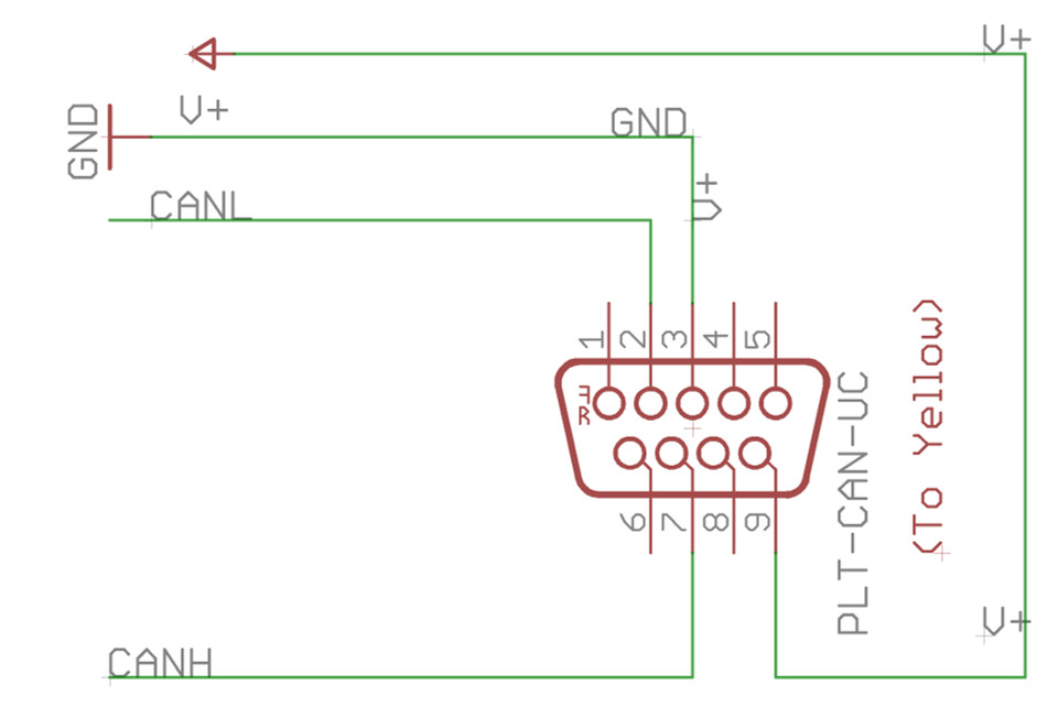
Figure 1 – Wiring for DE-9 User’s Cable to connect to Pilot’s yellow DE-9
Pilot-CAN Wire/Pin Assignment
Important: Pins 1 and 8 MUST not be wired on the end system side, they are internally connected the Pilot’s reprogramming interface and any voltages or signals on these lines will likely damage the unit.
|
Pin |
DE-9 Female User Cable |
|
1 |
DNC |
|
2 |
CANL (White) |
|
3 |
Ground (Black) |
|
4 |
DNC |
|
5 |
DNC |
|
6 |
DNC |
|
7 |
CANH (Green) |
|
8 |
DNC |
|
9 |
V+ (5V to 24V in e.g. car battery) (Red) |
DNC : DO NOT CONNECT