

Speed and Cadence sensors connect using ANT wireless communications that are standard in the Pilot range. Speed and/or cadence sensors are normally designed to be mounted on a bicycle; the sensor magnet on the wheel spokes and a sensor on the bicycle frame. By counting the pulses from the passing magnet, the speed the bicycle is traveling can be calculated (the only piece of extra information is the wheel circumference). Other uses include the hand-crank pedestals on racing yachts and any other similar hardware setups.
IMPORTANT: ANT+ certify three different types of Speed & Cadence sensors: Speed; Cadence; and Speed & Cadence. They are not the same ANT+ type but all three are individually supported by yellowcog's Pilot range.
There are large numbers of Speed and Cadence Products on the market but our Speed and Cadence Sensor help should assist with most of them.
You can easilty select a suitable ANT+ sensor by visiting the ANT+ directory.
You can choose to output any/all of the available data collected by the sensor via the Pilot by your chosen method. Commonly this would be serial, CAN bus or wireless.
If you need any help in choosing a yellowcog product or advice on how to build your next project then just email us.
Cadence Sensor
There are no settings for cadence.
Stream:
Cadence, Units: rpm, Bits: U16
Speed and Cadence Sensor
Streams:
Cadence, Units: rpm, Bits: U16
Speed, Units: 0.01kph, Bits: U16
Distance, Units: metres, Bits: U16
Properties
Wheel Properties
Some calculations require the wheel (or equivalent) circumference so cadence can be converted.
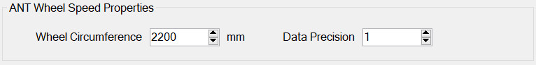
Wheel circumference: This is needed to calculate distance and speed
Data Precision: this is now deprecated.
ANT Properties
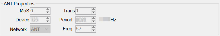
Most of the properties in this section should be left at their defaults if you are using a consumer sensor. If you are providing connectivity to your own custom device then the properties will need to be altered.
Available options are:
- Serial Number – set this to the serial number of the target peripheral or to zero for wildcard.
The remaining options should only be changed for custom sensors, standard sensors will cease to function if these options are changed; they are:
- MoS Type – Master or Slave type.
- Device Type – the number must match the peripherals device type.
- Network – Controls the Frequency Offset.
- Trans Type – this is specific to the way pairing is achieved.
- Period – the period between data exchanged in ticks of 1/32768 of a second. I.e. a period of 8102 means data is exchanged 4.04 times per second. Altering this from the sensors default will cause sporadic data transfer.
- Frequency Offset – defined by the network and is the offset from the base GHz frequency. Altering this will not alter the sensor frequency and will stop communications.
Wireless Device Properties
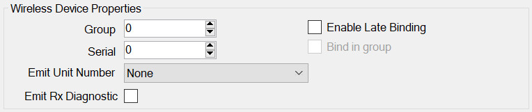
All wireless devices share some common properties.
- Group – see the page on Groups.
- Enable Late Binding – see Late Binding.
- Bind in group – see Late Binding.
- Serial – the serial number of the peripheral. It is not always necessary to have this set correctly but it assists in identification and pairing.
- Emit Unit Number as – in order to identify a device in subsequent output data it is useful to have the module transmit a stream called Unit Number. The number can be one of:
- Configured Serial Number – if this device is connected then this module will output whatever serial number you have entered into the config. If you have used a wildcard (serial number set to zero) then this option is not useful.
- Unit Number – this is an arbitrary configured value for this module. This is useful if the proper serial number is not wanted in the output data e.g. you would like your devices called “1, 2, 3…” not their true serials which may be opaque e.g. “43252, 243352… etc”
- Remote Serial Number – most devices will transmit their true serial number back, either via the transport protocol or in a separate message. As such, this option can be used with a configured serial number of zero but when the device connects the actual identity of the remote device is available. Note for ANT, this is the 16-bit serial number, for Bluetooth (+LE) this is the low 16-bits of the MAC address.
Basic Properties
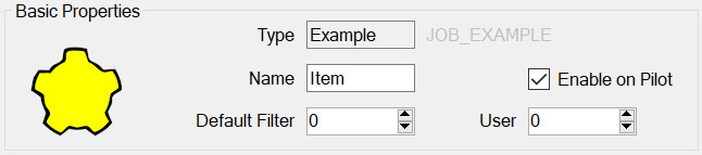
All modules have this panel. Options are:
- Type – is determined when first adding the module and governs which module properties can be configured.
- Name – used to identify the module in the module list but may also play a part on the embedded device, for example it may be required for it to appear in the outputted data.
- Enable on Pilot – if this is set then this config item will be included and enabled when transferred to the Pilot. If not, then it will still be editable on the PC but will not be used by the Pilot.
- Default Filter – see Streams, Advanced Concepts.
- User Number – This can be used to identify this module elsewhere in the system. For example, by outputting this number whenever the device is connected. In general, it can be left as zero.