

CAN bus is the standard for most data loggers. It uses a pair of differential wires and can work over long distances. Yellowcog’s Pilot devices work with all common CAN bus modes (up to 1MHz). The bus must be terminated at both ends with 120 ohm resistors to ensure correct operation. Note that none of yellowcog's devices provide this termination resistor so if you are connecting to a unused CAN port on a logger you must check if the logger can either be configured to provide the appropriate resistance or provide one yourself.
IMPORTANT: if you do not know the full specification of a CAN bus then any device, including all yellowcog devices, can cause the bus to fail.
Pilot uses CAN Products in many ways, including: CAN Module and CAN Serial Probe Module.
CAN Streams
The output of the CAN module is in two tiers: messages that each have an (hex) ID and the message payloads (which can be more than one stream/value). See Streams and Filters for information on the fundamentals of data exchange.
See notes on CAN Endianness if the data you receive is not as you expect. You might also enjoy: Binary, Decimal and Hexadecimal.
Messages can be added with the main “Add” button. This will create a blank message that can then be configured to contain the required data. If a message is no longer required then the “DEL” button will remove that message.
The main options for each message are:
- Message ID – this is the ID that the host bus is expecting to receive. CAN is a prioritised protocol meaning that the value determines which messages are more important – the lower the number the higher the priority. This means that in a system with existing communications it is important to set the message priority such that it does not interfere with more important data. On a closed bus (no other peripherals other than host and Pilot™) it is acceptable to assign arbitrary numbers.
- Update Rate – the frequency that the Pilot™ outputs the message.
- Length – this is controlled by the payload. The length can be changed using this numeric box between the limits (zero – empty message, to 8 – the CAN maximum). This value will also update to complement changes made to the payload section below it.
- MSB/LSB First – defines the bit ordering. MSB puts the most significant bit of the number first i.e. the highest bit is the first to be transmitted onto the bus. See section on CAN Endianness.
- Show Maths – if maths operations on each stream are required then checking this box will reveal the editors. Uncheck to save on screen space while editing.
- Bits – Each stream loaded into the message can be set to the required number of bits. Currently only multiples of 8 bits can be set. Set the required bits for each stream. If increasing the number of bits, the other streams will be pushed along the packet. If decreasing the number of bits the other streams will be pulled back. If you wish to reduce the width but leave the other packets it is necessary to configure in a VOID stream of the required width.
- Filter – See Streams, Advanced Concepts.
- Stream – See Streams.
- Maths – click this to reveal the Maths pop-up window
Helpers
There are a few helper options presented in the top right of the streams section:
Import – opens a File Open dialogue and will read in a DBC file. Not all settings are imported but the main set of streams and CAN formatting are imported. IMPORTANT: the stream names in the DBC file must conform to the naming conventions of the Pilot™ systems. i.e. Heart Rate will be mapped to the standard HEARTRATE stream.
- Sort – Sorts the messages into ascending CAN message ID order.
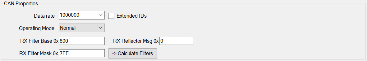
CAN Properties
Also see: CAN Endianness
The CAN bus must be configured to match the requirements of the host CAN bus. The options are:
- Data rate – fundamental to interoperability, the rate, in Hertz, that communications occurs at. All common data rates are supported.
- Extended IDs – the CAN bus specification was altered to allow a larger range of addresses to be used. To use the extended mode this checkbox should be set. It is still common to use the original mode. The only way to discover the required mode is to check the mode of the host bus via its configuration software or specification documentation etc.
- Operating Mode – this should be set to “normal”. Other modes include “Listen”, if for example no data is to be transmitted.
- Rx Filter Base – Used to define the first message number in the range Pilot™ will receive (Rx) and process.
- Rx Filter Mask – Combined with the Rx Filter Base to control processing.
The Calculate Filters button uses the currently configured receive streams to calculate the optimum receive filter. Having the wrong filter would result in missing one or all incoming packets.
Basic Properties
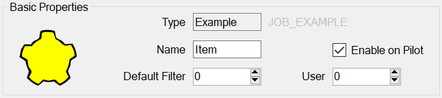
All modules have this panel. Options are:
- Type – is determined when first adding the module and governs which module properties can be configured.
- Name – used to identify the module in the module list but may also play a part on the embedded device, for example it may be required for it to appear in the outputted data.
- Enable on Pilot – if this is set then this config item will be included and enabled when transferred to the Pilot. If not, then it will still be editable on the PC but will not be used by the Pilot.
- Default Filter – see Streams, Advanced Concepts.
- User Number – This can be used to identify this module elsewhere in the system. For example, by outputting this number whenever the device is connected. In general, it can be left as zero.